How to model any Geodesic Polyhedron in CAD
This page discusses how to model any geodesic polyhedron accurately in CAD software.
Recently, I had to model a 6V icosahedron geodesic sphere for a freelance job, as I started researching, I could not find a clear way of how to model it. There are several online geodesic calculators which spit out the correct member lengths and angles but do not explain how these values are calculated. I didn’t want to use online calculator values as I needed the model to be parametric, meaning I could easily adjust the scale of the CAD model without having to refer to an external tool. I also found a few videos online that demonstrated how to model various geodesic domes, but they did not provide a clear explanation of the underlying geometry or mathematics.
I found that once you know one specific feature of the geodesic polyhedron geometry, it is actually quite simple to model.
All geodesic spheres, or domes, start with some base polyhedron. Usually this is a a platonic solid to give symmetry, such as an icosahedron, dodecahedron, octahedron, tetrahedron etc, but can also be other variants such as a truncated icosahedron. This Wikipedia page is a good reference
The below steps outline how I modelled a 5V geodesic icosahedron model. However, the general steps will apply to any base polyhedron for any frequency subdivision.
I have used SolidWorks 2020, but the principles apply to all CAD software. For reference, you may download my files for free at the bottom of this page (.sldprt & .step files)
Step 1.
You must start with the base polyhedron you wish to use. I have used an icosahedron, I briefly explain in my YouTube video here how to model an icosahedron.
On one of the surfaces, using a sketch, divide the face into smaller triangles, according to the frequency subdivision you wish to use. For my example, I have used a division frequency of 5, also known as 5V. This requires 5 triangles along each edge, as shown below. When drawing this, make sure the edge lengths of all small triangles are the same (using the ‘equal length’ sketch relation in SolidWorks). For reference, a 5V division has 5x5=25 smaller triangles. An 8V, for example, would have 8x8=64.

Step 2.
Create a sphere which encloses the icosahedron. The sphere’s center point should be coincident with the icosahedron’s center point. From an orthogonal first angle view (side view, front view etc) the outer edge of the sphere should also be coincident with the outer most points of the icosahedron, as per image below. This sphere will soon be used as a reference.

Step 3.
Using a 3D sketch, start by drawing a line from the icosahedron/sphere center point, towards the outer surface of the sphere. This line should pass through a vertex (corner) of one of the small triangles previously sketched. To do this in SolidWorks, select the line you have just drawn, hold down the ctrl button, and select the vertex. You can then apply a coincident relationship.
Next, select the end point of the line just drawn, holding ctrl also select the surface of the sphere, then apply an “on surface” relationship. Note, setting the length of the line to match the radius of the sphere also achieves the same goal and I found this to be a bit more stable in SolidWorks.
Repeat this process until each vertex of the flat subdivision sketch has a straight line passing through it which terminates at the sphere’s outer surface. The result should look something like below.
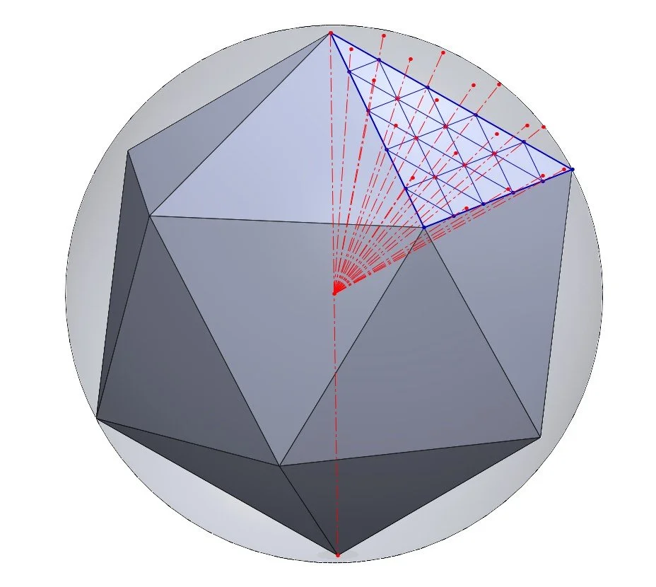
What we have created above is a projection of the flat subdivision sketch to the spherical surface, specifically, the vertices of all the small triangles. This projection step is the “secret” tip that I could not find in my research. This step can apply to any base polyhedron with any subdivision.
Step 4.
Next, using a new 3D sketch, draw a line between each of the end points of the projection lines. This produces the projected subdivision pattern onto the sphere. Note, this projection stretches the triangles in the center more so than the ones near the edges.


Step 5.
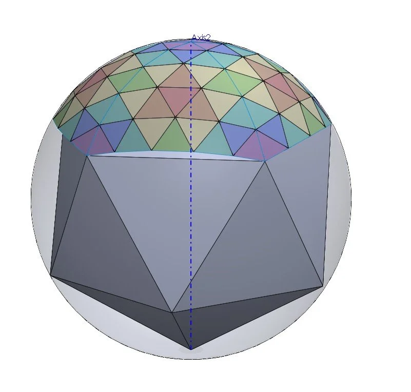
I then used the boundary surface feature to turn this 3D sketch grid into a series of flat faces. I knitted these faces together to give a single surface body. At this point I applied colour appearances to the smaller surfaces, this step is obviously not necessary but does look nice.

Step 6.
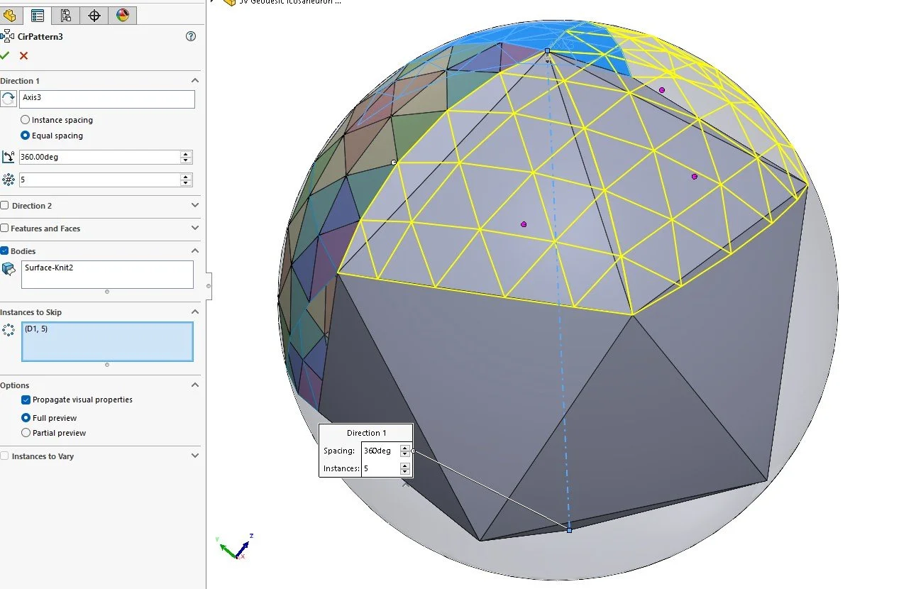
I made a central axis using two opposing points of the icosahedron as references. Using this axis, I revolved the surface body around 360 degrees, with 5 equally spaced instances. This gives the upper section, as per images below.

Step 7.
I then created more axes as needed and repeated this process of revolving a surface body. I used the “skip instance” option to avoid duplicating surfaces in the same location. SolidWorks represents each instance with a magenta colored dot, you can select this dot under “instances to skip” to remove desired instances of the pattern.
Step 8.
Repeat this process of creating axes and revolving a surface body until you have built up the entire geodesic sphere. For a geodesic dome, you can of course truncate the sphere. The colors I have used represent the surface areas of each small triangle, triangles that are the same color have the same surface area.


Step 9.
Finally, select all 20 surface bodies and knit them together, you may also wish to make it a solid body. The model scales with the size of the enclosed icosahedron, meaning if you go back and change the size/dimensions of the icosahedron, the geodesic will also update accordingly.
This process can be applied to create a geodesic sphere from any base polyhedron with any frequency subdivision.
Reference Files
You may download my files below for reference (.sldprt & .step), you will need at least SolidWorks 2020 to view my feature tree.
If you have found this guide useful you may wish to donate towards my work. Any amount is greatly appreciated. I am an individual that makes CAD related content in my free time between freelance jobs.
Thanks!
