Compact Bionic Hand Update
It’s been quite a while since I made my last update video on the compact bionic hand I have been designing. If interested you may view the playlist of videos here
The truth is the project quickly became too time consuming, expensive and difficult for me to continue pursuing, especially trying to manage working full time along with other life commitments.
In this blog post I’ll explain why I ended up stopping work on the project and the challenges I ran into. But first, I just want to give a quick run down of what I was trying to achieve in the first place. Since working for many years as a design engineer my skills have vastly improved from that when I was a University student, the time when I design the first myoelectric 3D printed prosthetic arm.
I wanted to use my new skills to design a compact bionic hand that offers a relatively high number of degrees of freedom whilst housing all necessary components in a small form factor. I decided to give the fingers one degree of freedom each but deemed it was important for the thumb to have three degrees of freedom. This would hopefully allow for the potential of an opposable thumb to be more realised. In my previous design (and most commercial prosthetic hand designs) the thumb just has 1 degree of freedom so cannot manoeuvre around all that much. I also wanted the wrist to be able to rotate and flex and I felt these degrees of freedom where achievable and would also add significant functionality to the design.
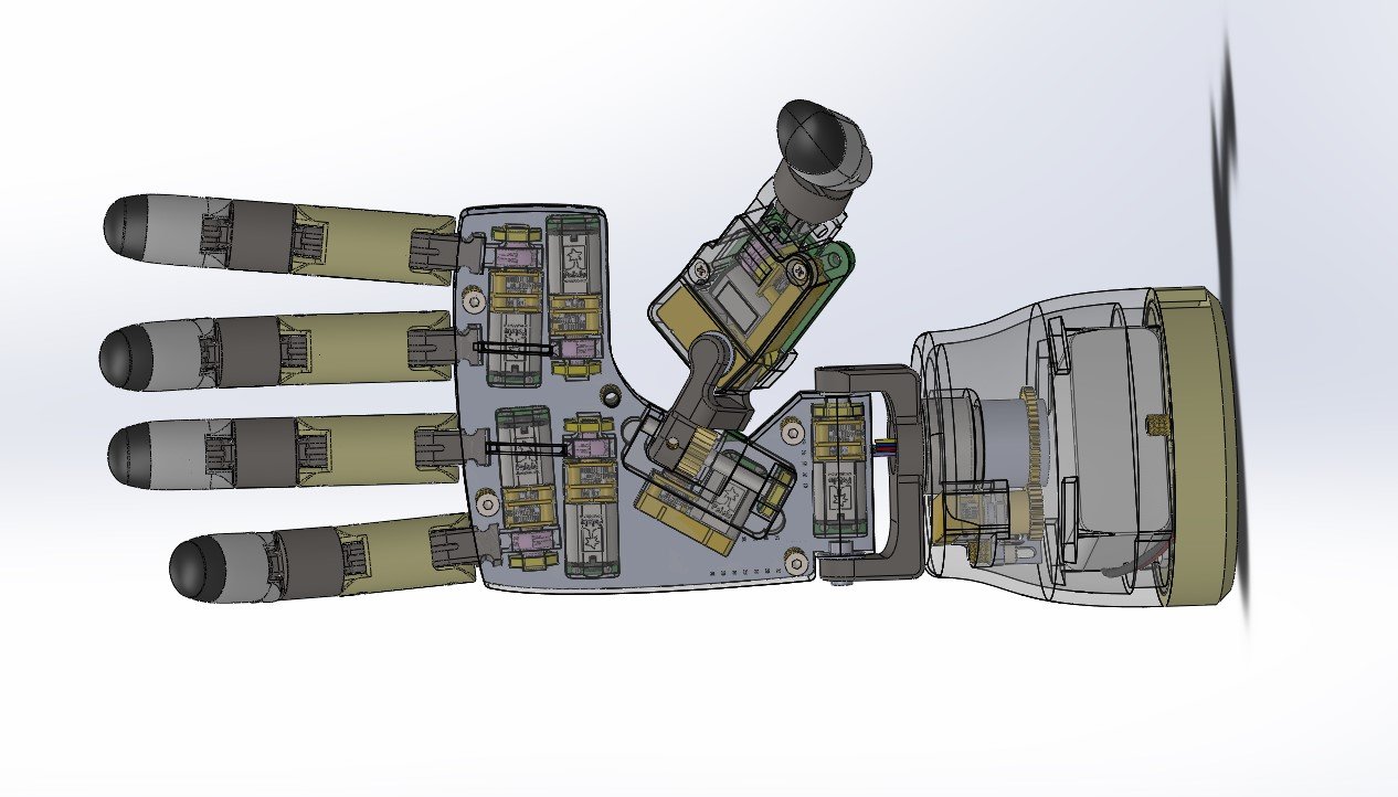
As you can see in the images below I went for a design where I directly placed the motors inside of the palm and wrist sections to achieve all these degrees of freedom. The battery was placed at the base of the wrist and a custom electronics PCB was to be mounted on the back side of the palm and thumb.

All in all my hope was that this would produce a compact bionic hand with a relatively high number of degrees of movement. Most bionic hands that have many degrees of freedom utilise the entire forearm either to house motors or electronics. The problem I saw is that if a person only loses their hand but still has their forearm intact, they cannot use a bionic hand which offered high mobility (e.g. extra thumb and wrist movement). This was simply because nothing like this exists to this present day (to the best of my knowledge). So with this in mind I set out on the design.
It took me a fair amount of work doing the mechanical design but the real roadblock came when I made some progress with the electronics design. In total there were nine micro motors I had to control. This required a motor controller chip (H-bridge) for each motor, each of which requires two inputs, enable & phase (motor direction) as well as the power lines from the chip to each motor. Also, it was important I/the software had some way of knowing whether or not the fingers were open or closed and the wrist was rotated or flexed etc. Essentially this means we need some way of knowing if the motors have moved and if so what angle have they rotated to. I decided to integrate a small micro potentiometer onto the shaft of each motor which would give a variable resistance depending on its rotational angle. So one potentiometer for each motor was also needed.
I also wanted to include some small force sensors on the finger tips but decided that wasn’t absolutely essential, at least for a first prototype. So all in all the electronics requirements weren’t too crazy, just control nine micro motors and read nine potentiometers. However, it quickly became difficult when I realised how little space I had to work with. To avoid placing electronics in the forearm section and keeping the system compact I had to use only the space on the back of the palm. Due to the nature of the mechanical design the thumb mechanism ta away about one quarter of the available space.
For the controller of the system I wanted to start simple maybe using an Arduino nano but it simply didn’t have enough output control pins. Something like an Arduino uno was far too big. Another complication was that I wanted the PCB and the cover over it to be relatively flat and flush. I didn’t want the electronics to be bulging out the back of the hand, to me that would have looked weird and taken away from the point of it being a compact design. For this reason I also found that it had to be a PCB with only surface mount components, through hole components lead to a body that was too thick. This is why teensy boards weren’t really suitable because even though they were small enough I couldn’t afford to mount a through hole board to my custom board.
I eventually found some small surface mount friendly boards featuring an ESP32 controller, I found the TinyPICO Nano was suitable for my needs. From here I started designing a custom PCB. Broadly speaking it consisted of the TinyPICO controller, H-bridge motor controllers, an analog multiplexer (to have enough inputs to read the potentiometers) and a GPIO expander to have enough outputs to control the motor enable functions.
The schematic below is what I came up with using Easy EDA. Note, I’m primarily a mechanical design engineer, my electronics skills and experience is far inferior, there may be many errors with the below schematic.
For those interested in the PCB files I started working on info can be found below:
PCB details
PCB editor - will need an Easy EDA account
PCB includes:
- Battery or USB power input & voltage regulation
- Small controller to control movement commands and actuate the motors. I used a tiny pico nano but something like a small ESP32 board could also be suitable
- Several motor drivers (DRV8835DSSR)
- Multiplexer (CD74HC4067SM96) to read potentiometer for each motor. Controller must select which channel to read on the multiplexer using s0-s3. Output is an analog voltage passed to controller ADC
- I2C GPIO extender (SX1509BIULTRT) used to control the enable function of the motor controllers. This is required simply because the controller did not have enough IO, another controller may have more

Another challenge was the layout of the PCB itself, I had a lot of traces to fit in a small area. You can see the layout I came up with below. Note that I never got around to completing this.

You might notice some connector pad patterns at the bottom and middle left. The bottom was to connect to some lines coming in from the slip ring in the wrist. Specifically these would be for the power from the battery in the wrist, as well as the wrist rotation motor and potentiometer. The pad on the left side was to connect to a small PCB on the thumb which would contain a motor controller chip for the thumb ‘flexion’ and ‘grasp’ motors.
Sadly at this stage I started to realise I was in over my head with this electronics design. To start with I knew I had to include some bulk capacitors on the power input but didn’t really know what size capacitors to use. I asked on some forums for some recommendations but those sizes would have been too big to fit in the compact nature of the design. Also, I have little to no experience with surface mount soldering and I knew it would be extremely challenging for me to get all the soldering joints right on the first go. It would even be hard for me to debug and I realised I would have to invest in some good equipment to even attempt this. Finally, as my electronics design experience is limited, this was by far the most complex circuit board I had designed and I was certain there were probably quite a few mistakes in my design. To top it off several of the components like the motor controllers were out of stock.
I realised it would be a challenging, time consuming and expensive road to build this first custom PCB and it would be a lot of debugging and probably a redesign or two before I really got it working. Even at that point to really make use of the extra degrees of freedom in this design the software and control side of things would have to be pretty involved. I was planning on attempting some form of sensor fusion between EEG and EMG for the users to implement. Something along the lines of the user wearing an EEG cap and when they ‘think’ of a certain grip pattern the system recognises that, at which point they use the EMG sensors, flexing some muscles somewhere, to activate the selected grip pattern. Maybe a certain grip pattern could be useful for turning a door handle, whilst another better used for operating a computer mouse etc. This was a whole other can of worms and even still wouldn’t necessarily utilise the extra mechanical functionality in a practical manner.
So I kind of put the project on hold and then later unfortunately experienced some really bad heart problems, pericarditis, which was the final nail in the projects coffin…
I have still received some emails and comments from people interested in this project and hoping for an update. While I probably won’t return to working on it anytime soon, nothing is out of the question in the future. For now I would like to share my design for anyone who would like to pick up where I left off. I charge a small fee for my designs which just helps me fund current and future project buy helping pay for motors, 3D prints, electronics etc.
I will make another blog post where I provide more specifics about the mechanical design and go over each mechanism and some of the challenges.
If you made it this far thanks for reading!
Mahdi